
i3D Workbench · Input tool Available
Digitized Data to 3D
Import digitizer / probe scan files and convert them to a 3D mesh.
Digitized Data to 3D converts touch-probe digitizer and scanner files (.nc, .g00, .dig, .pun, up to 300 MB) into a binary STL mesh. It compensates for the probe stylus shape (flat or round) and diameter, offers reduction (1–15), smoothing (0–7) and scale (0.1–10), and can send the model straight to MillX to mill a copy.
| Group | Input |
|---|---|
| Status | Available |
| Input | .nc, .g00, .dig, .pun |
| Output | STL (binary) |
| Max upload | 300 MB per file |
| Runs in | Desktop browser with WebGL 2 (Chrome, Edge, Firefox) — computation on Ahaborg's C++ backend |
| Billing | Pay-per-use credits, no subscription |
| Documented in | i3D Workbench User & Reference Manual v2026.10 |
Overview
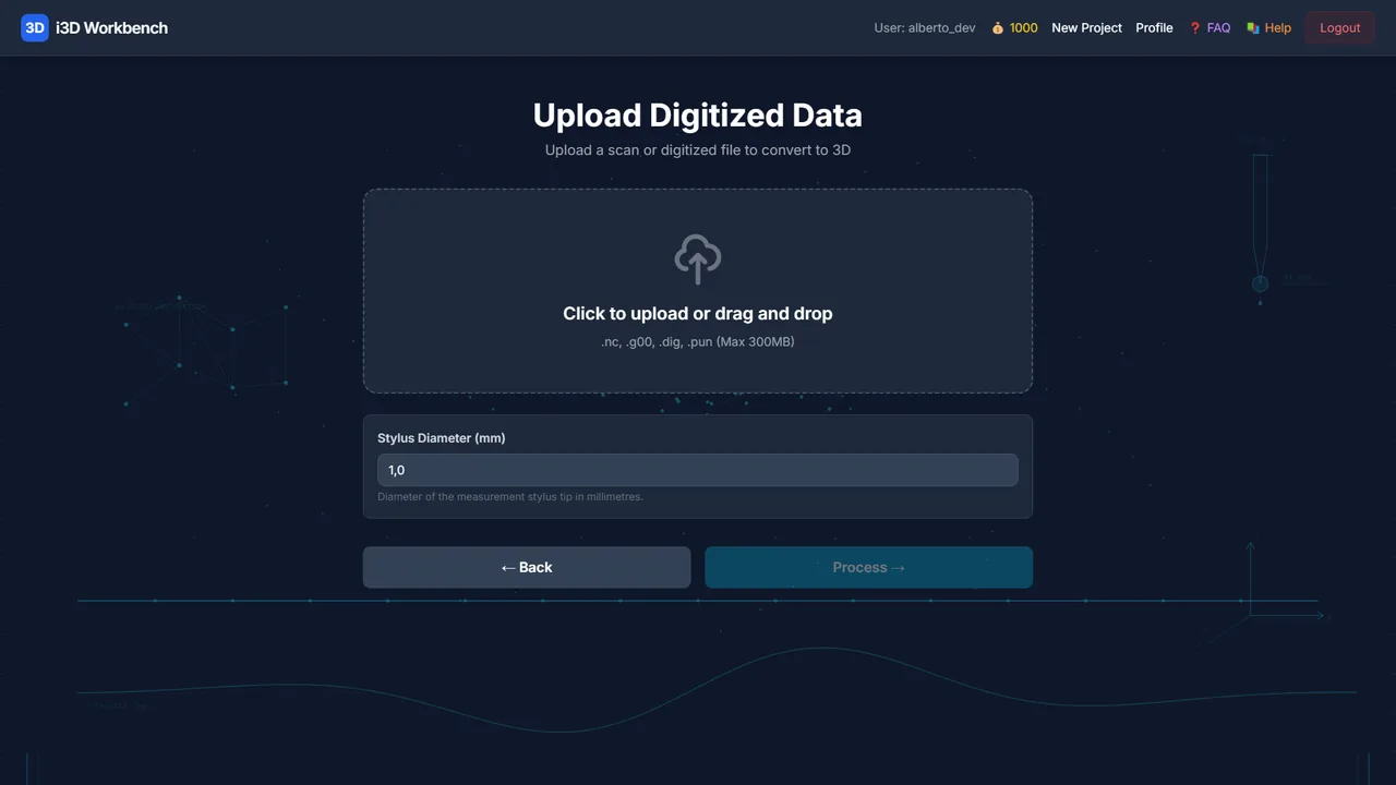
Upload a file produced by a touch-probe digitizer or scanner. The file is sent to the server, converted into a surface, and opened in Model View, where you set the stylus geometry and processing options and export an STL — or send the model straight to MillX.
Step by step
- Open Digitized Data to 3D from Select Mode.
- Click or drag-and-drop the scan file (
.nc,.g00,.dig,.pun; max 300 MB) and click Process. - Model View opens with the reconstructed surface. Check Object Size.
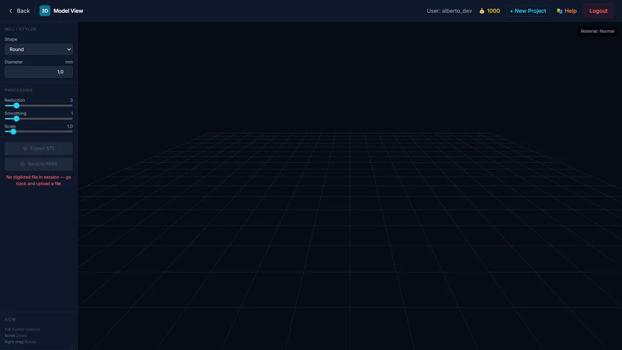
- Set the Mill / Stylus shape (Flat / Round) and diameter used during digitizing — the server compensates the probe geometry.
- Adjust Reduction, Smoothing and Scale. Each change recomputes the mesh on the server (debounced).
- Click Export STL to download the mesh, or Send to MillX to continue with a milling job.
Controls
Upload page
| Control | Range / values | Default | What it does |
|---|---|---|---|
| Upload area | .nc .g00 .dig .pun · ≤ 300 MB | — | Click or drag-and-drop a digitized file. |
| Process | — | — | Uploads the file to the server and starts the conversion. Appears after a valid file is selected. |
| Remove | — | — | Clears the selected file so you can pick a different one. |
Model View — Object Size
Read-only X / Y / Z size of the digitized object in mm.
Model View — Mill / Stylus
| Control | Range / values | Default | What it does |
|---|---|---|---|
| Shape | Flat · Round | Round | Tip geometry of the probe/stylus used when the data was captured. |
| Diameter | — | — | Stylus diameter (mm). Needed to compensate the probe offset on the reconstructed surface. |
Model View — Processing
| Control | Range / values | Default | What it does |
|---|---|---|---|
| Reduction | 1 – 15 | 3 | Mesh simplification. Higher = fewer triangles. |
| Smoothing | 0 – 7 | 1 | Surface smoothing passes. |
| Scale | 0.1 – 10 | 1.0 | Uniform scale applied to the exported model. |
Model View — View
Shading presets 1 PBR · 2 Matcap · 3 Curvature · 4 Normal (number keys). Right mouse orbits, middle mouse zooms.
Actions
| Control | Range / values | Default | What it does |
|---|---|---|---|
| Export STL | — | — | Computes the final mesh on the server (/digitized/export-stl) and downloads it; the status line reports the triangle count. |
| Send to MillX | — | — | Stores the STL on the server and opens MillX with it already loaded. |
Tips & tricks — Digitized Data to 3D
- Enter the real stylus diameter: with a round tip the raw points lie one radius above the true surface, and the compensation only works if the value is right.
- Start with Reduction 3 and Smoothing 1. Raise Smoothing only to kill probe noise (“stairs”), because every pass also rounds real edges.
- Look at the model in 3 Curvature shading to spot scan artifacts — they show as sharp dark lines.
- Use Scale for unit fixes (×25.4 for data captured in inches) rather than scaling later in CAM.
- Prefer Send to MillX over download + re-upload: the mesh is already on the server and Calculate starts immediately.
Troubleshooting
“Please upload a supported file format”.
Only .nc, .g00, .dig and .pun are accepted. Export your digitizer data in one of these formats.
The surface is inverted or mirrored.
Check the axis convention of the digitizer. Mirroring can be corrected later in MillX by rotating the view, or in your CAD before re-uploading.
Works well with
Tools that chain with Digitized Data to 3D — see the workflows.